PiTrac Assembly Guide
This document explains the process of building a typical PiTrac DIY Launch Monitor (LM). This process includes the assembly of all physical components, including the 3D-printed parts and hardware such as cameras and Raspberry Pi computers.
Important: This document refers to the calibration steps for the camera sub-system, which should be consulted prior to building the enclosure. Calibration is most easily done as the LM is being assembled because it allows easier access to cameras and camera mounts before the LM is completed. See Camera Calibration for details.
Overview
The LM is not a simple, complete kit that just requires attaching Part A to Part B. Instead, it’s a general design that we hope builders will customize, adapt and improve depending on their goals and skills. The particular parts referenced here may not even be available when you build your LM. This document is a guide for building what is expected to be a ‘typical’ PiTrac LM.
Conventions
- Direction References: Left/right/back/front refer to the LM as it faces the user, with the camera side toward the builder
- Pi-side: Right half where the Pi’s, cameras, and Connector Board are placed
- Power side: Left side where power adapters and cables are contained
- Terminology: 3D parts use a house analogy - curved outside parts are “walls,” flat horizontal parts are “floors”
Note: Enclosure terminology diagram referenced in original documentation is missing from image files.
Tools Needed
Essential Tools
- M2.5, M3, M4, and M5 hex wrenches (both right-angle and straight)
- Needle-nose pliers
- Medium-sized Phillips screwdriver (at least 6” length)
- Soldering tools
- Wiring tools (wire strippers, clippers, etc.)
Optional Tools
- Magnifying, lighted headband and/or magnifying desk light
- Dremel tool for trimming parts if needed
- Soft/hard rubber hammer or mallet
Parts and Materials
- See the Parts List for complete component list
- 3D-printed enclosure parts
- Solder, flux, flux-cleaner
- Wires (stereo-speaker wire recommended for higher-voltage portions)
Optional Materials
- Sandpaper and sanding block
- Non-IR-reflective cloth material (black felt) for backdrop
- Note: Some black cloth appears white under IR light - test first
Assembly Instructions
1. Printing the Enclosure Components
First, see the individual printing and assembly instructions for each 3D part. The 3D printing is a multi-day project due to part sizes.
Pro Tip: Having hardware components in hand before printing allows you to customize part models to fit your specific components. For example, different LED power supplies may require different mounting holes.
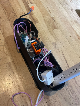
2. Base Layer Assembly
The base layer is the foundation that touches the ground. It consists of two wall halves that connect in the middle, with floors inserted into mounting risers.
Wall Halves and Lower Component Bays
-
Prepare Pi-side half-join: Place two M3 nuts into the indents on the Pi-side half-join pads. Use temporary bolts from outside to pull nuts into indents if tight. Tape helps hold nuts in place.
- Install LED power supply: Install before joining wall halves (it’s heavy, so keep it low).
- Place in right-hand half
- Secure to floor risers with four M4 x 12mm screws
- Use recommended supply or similar
- Add quick-connect to output wires with clear polarity markings
- Input should have 3-prong plug for utility strip
- Install network switch: If it fits and allows cable connections, place in Power-side bay now. Route cables:
- One cable out the back of LM
- Two cables to Pi’s on right side
- Join base halves: Connect using two pairs of M3 x 16mm bolts and nuts.
External (Tee-up) LED Lighting
Install LED lighting under the base layer overhang for Camera 1 visibility:
- Mount LED strips: Using recommended strips, create double brightness by using two layers
- Position first layer: Tack down one end on left side, stick below overhang, push ~4 inches into right LED port
- Add second layer: Stick second layer just below first for double LED rows
- Route power: Pull USB power plug through left LED port, either to internal power strip or external power for independent control
- Secure strips: Use zip-ties through small holes at base layer ends
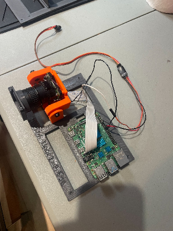
3. Camera 2 Assembly (Flight Camera)
Camera 2 is the bottom camera that captures the ball in flight and requires modifications.
Camera Modifications
WARNING: These modifications void the camera warranty and are delicate operations that can damage the camera if performed incorrectly.
-
Remove IR filter: Use official RPi instructions
-
Add external triggering: Follow RPi external trigger guide
- Resistor removal is particularly difficult - use magnifying light and steady hands
- Practice on old surface-mount PCBs first
- Use quick-connect wires with jumper pins for easier connection/disconnection
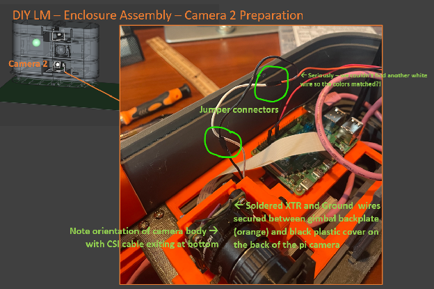
- Strain relief: Add thick glue drop over wire/solder junction. Run wires down from camera top and pinch between camera and gimbal backplate.
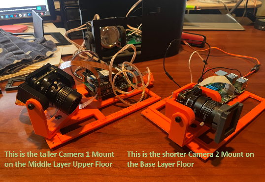
Camera Mount Assembly
- Mount selection: Use shorter mount for Camera 2 (doesn’t need to point downward like Camera 1)
- Cable first: Attach CSI cable before bolting camera to backplate - lock cable securely
- Threading: Carefully thread CSI cable out back of mount without pinching
Add IR Filter
- Filter holder assembly: Glue two parts together using registration wings for alignment
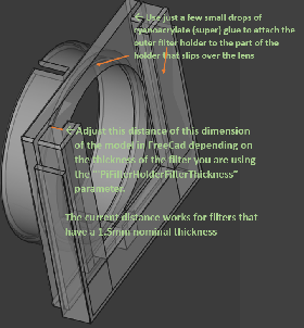
- Install filter: Insert visible light-cut filter, attach holder to lens with opening at top
4. Pi-side Base Layer Floor
- Mount Camera 2: Use M5 bolt and nut with CSI cable and trigger wires in place
- Mount Pi 4/5: Use 4x M2.5 x 12mm bolts and nuts (nuts on bottom). Insert MicroSD card before mounting
- Connect camera CSI cable to Pi
- Connect camera GND to Pi pin 9
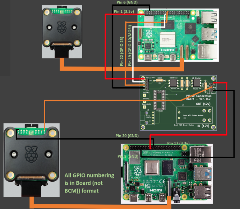
- Create Pi 2-to-Connector-Board ribbon cable:
- Fashion 3-wire harness with female plugs each end
- Use black/red wires plus third wire for Camera 2 XTR
- See wiring diagram reference below
Quality matters: Low-quality wiring harnesses can cause random, difficult-to-diagnose problems. Ensure firm connections and make cables slightly longer than necessary.
Recommended: Pre-crimped ribbon cable kit
5. Joining Base Layer Floor Halves
The two base floor halves join with an overlapping lap joint:
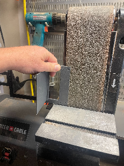
- Prepare power-side floor: Remove printing supports and smooth lap joint area. Belt sanding may help.
- Pre-place screws: Insert 6x M3 x 10mm screws a few turns into power-side holes and right-most Pi-side holes
- Join floors: Slip power-side lap joint between camera base and Pi-side lap joint
- Install assembly: Place joined floors into base walls, aligning lap joint in middle
- Secure floors: Use M3 x 10mm screws into wall mounting pads
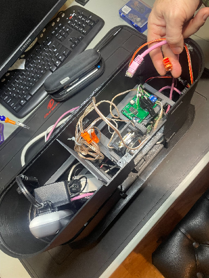
6. Complete Base Layer
- Route power cable: Thread from power strip down through support and out base hole (tight fit - do first)
- Connect Pi power: Route from Pi power supply to Pi board
- Connect network cable: Route one network cable to Pi
7. Prepare for Middle Layer
Route cables that will connect to Middle Layer components:
- Network cable from switch (to Pi 1 on middle layer upper floor)
- 3-wire harness from Pi 2 (to Connector Board on middle layer lower floor)
- LED strobe power cable (to LED strobe on middle layer lower floor)
Route these cables to the right side for easier middle layer installation.
8. Camera 2 Calibration
Important: Calibrate Camera 2 now while easily accessible. See Camera Calibration Guide.
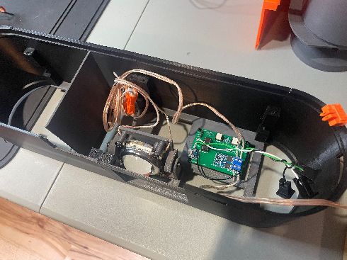
Middle Layer Assembly
The Middle Layer has two wall halves and two floors on the Pi side: lower floor (strobe LED and Connector Board) and upper floor (Pi 1 computer and Camera 1).
1. Build Strobe Assembly
See LED Strobe Mount instructions.
2. Build Connector Board
See Connector Board instructions.
Critical: Attach 12V IN/OUT wiring pairs and 4-wire harness to Connector Board screw terminals before mounting the floor. Access becomes difficult after upper floor installation.
3. Join Middle Layer Wall Halves
- Prepare nuts: Place 4x M3 nuts in Pi-side half-join pad indents (use tape to hold)
- Join halves: Use 4x pairs of M3 x 16mm bolts and nuts
- Check fit: Sand half-join areas if gaps exist
4. Middle Layer Lower Floor Assembly
- Mount Connector Board: Position with 4-pin header on left, writing upright. Secure with 4x M3 x 8/10mm self-tapping screws
- Mount strobe assembly: Use M5 bolt from below through M5 nut in floor indent. Position LED power wires through side holders, face strobe straight out, tighten while accessible
5. Install Lower Floors
Mount both Pi-side and power-side lower floors to bottom of lower mounting pads using 4x M3 x 10mm self-tapping screws each.
Connect 5V micro-USB power to Connector Board from power adapter in left bay.
6. Camera 1 Assembly
Camera 1 is similar to Camera 2 but:
- Points downward steeply (uses taller riser mount)
- Uses visible light (no modifications needed)
- Requires different adapter cable for Pi 5
7. Pi-side Middle Layer Upper Floor
- Mount Camera 1: Use M5 bolt and nut with CSI cable secured first
- Mount Pi 5: Use 4x M2.5 x 12mm bolts and nuts (nuts on bottom). Install NVMe/SD card first. Consider active cooler for development use
- Connect camera CSI cable: Use Pi 5-compatible cable (smaller connector format)
8. Install Upper Floor
- Guide cables: Route 4-wire harness and second network cable to right as you place upper floor
- Mount floor: Secure to side pads with 4x M3 x 10mm self-tapping screws
- Connect wiring:
- 4-wire ribbon from Connector Board to Pi 1 GPIO (see wiring diagram)
- Network cable to Pi 1
- Pi 5 power supply from power-side
9. Mount Middle Layer on Base Layer
- Prepare cables: Ensure all base layer cables (3-wire harness, network, LED power) are positioned right
- Guide power components: Route utility strip and power adapters up left side void
- Thread cables: Guide base layer cables through right side space as middle layer is positioned
- Check clearances: Ensure no wires will be pinched when layers connect
- Connect layers: Insert middle layer click-tabs into base layer tabs. Set into back first, then pull front of base layer outward to help engagement
Safety: Resist hitting layers together - middle layer top is sharp!
10. Connect Power Systems
-
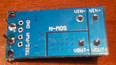
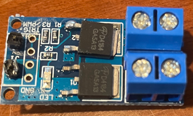
LED power supply to Connector Board: Connect LED power output to “IN (12V)” terminals on Dual MOS switch
CRITICAL: Double-check polarity! Reversed connection can destroy LED. Use clearly marked wires and keyed connectors when possible.
-
Connector Board to LED Strobe: Connect “OUT (12V)” terminals to LED strobe
WARNING: Do NOT connect strobe directly to LED power supply output - this could melt the strobe or worse!
-
Connect Pi 2 and Camera 2 harnesses: Connect wiring from base layer to correct Connector Board header pins per schematic
11. Secure Layers
Secure base and middle layers with M3 x 6mm self-tapping screws in 4 interface holes. Consider dulling screw tips for safety.
Camera 1 Calibration
Before installing the ceiling, calibrate Camera 1 using the Camera Calibration Guide.
Top Wall (Ceiling) Assembly
- Connect ceiling halves: Use 4x M3 bolts and nuts
- Install ceiling: Snap onto middle layer top, secure with 4x M3 x 6mm self-tapping screws
- Dull screw tips for safety
Final Steps
Add Front Window
Install 15.5cm x 24cm plexiglass anti-strike window by sliding into mounting slots. Window should be far enough from cameras/strobe to protect expensive components from ball strikes.
PiTrac Badge/Logo
- Print components: Back plate at full size, letters at 99% size for better fit
- Color scheme: Use preferred colors (see reference image)
![]()
- Assembly: Use rubber hammer to tap characters into place. Friction holds parts, but cyanoacrylate glue provides permanent bond
- Mounting: Use 2-sided tape (rough surfaces don’t glue well)
Next Steps
Once assembly is complete, proceed to the Start-Up Documentation for software installation and configuration.
Troubleshooting Tips
- Tight fits: Use Dremel tool carefully to trim parts if needed
- Stripped threads: Consider brass threaded inserts for frequently-removed screws
- Cable management: Leave extra length in all cables for easier assembly/disassembly
- Component protection: Always verify polarity before connecting power components